

Bolts: The Robot
Our goal was to make Bolts large enough that different attachments could be added down the road. but agile enough to make tight turns without tipping over.
We have taken all the skills we have learned over the past 2 years of classes and applied it to building a robot that meets the requirement's set forth for the 2024 LATC Robot Games. We applied out knowledge of mechanical drives, welding, 3D printing, designing, CAD drawing, microcontrollers, Arduino/ESP32 coding, soldering, motor controls, troubleshooting, and robotic engineering to get our robot up and moving.
Below we have shared our journey bringing Bolts to life.
First drive chain assembly
01
Drive chain
Creating a vision and executing a drive train was our first task. We chose to use 35 roller chain and sprockets to create our driving system.
After some work on the coding Bolts was easily controlled by even the youngest RC enthusiast in the house.
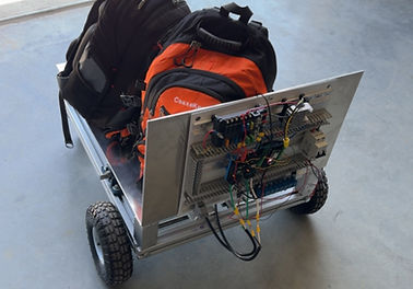
Bolts transporting our backpacks and tools
The youngest RC/Robotic enthusiast taking Bolts for a quality test run.
02
Hill Climb
Our first 2 tries at going up the hill climb were unsuccessful, after 3 times of changing the gear ratios we found the perfect match of speed and torque. Bolts made it up the ramp no problem on the 3rd try.
First failed attempt at climbing the hill
Successfully climbing the hill!

Husky lens
03
Automated Course
The automated course challenge was done utilizing a husky lens and color recognition coding in Arduino IDE.
We initially tried using a simple line follow program but, quickly found that the lens was struggling with the line tracking and found the color recognition to work much smoother.
04
Basketball
My initial basketball design worked much better prior to mounting it to the robot, thus adjustments were made. Adding forks and a back stopper for loading the basketball, adding some 45 degree angles made it so we could get the ball loader to the ground. But this slowed it down and made it too heavy to launch the ball. I added a second motor to try and compensate for the added weight.

Original design drawing


Welding catapult
Mounting catapult
Completed catapult
Final design drawing, before modifications

Welding catapult

First draft golf drawing

05
Mini-golf
For mini-golf I went with a pretty straightforward simple design. I 3D printed a base to attach a motor to and and a club with set screw holes to attach to the motor.
Video of golf club functioning
Final draft golf drawing

06
Thread Nut on Bolt
Our vision for this task was to 3D print a socket split in half with springs for tension. Mounted on an ACME rod using the same method found on the 3D printers we built last year. It took several re-prints and redesigns to find a good version of the socket. We also faced challenges programming the stepper motors, relearning how to program to an ESP instead of an Arduino, additionally we had quite a few drivers blow on us.

3D printed socket
Socket mounted on ACME threads and armature

Gripper arm pieces
07

Pick and Place
I 3D printed a gripper systems that runs off a motor that spins 4 gears to open and close the arms. The arms have distal and proximal tips that I added foam to, this is to give the smooth surface some grip to pick up the gears.
